


In power system, protective relay is the key link to ensure that it can accurately and reliably detect and remove faults Section. The following are the detailed content and related steps of on-site debugging of relay protection devices compiled by our company, hoping to help debugging personnel Understand and master the relevant steps of device debugging.
1.Preliminary inspection and tool preparation :
1.1 Preparation before commissioning Understand equipment and systems: Be familiar with the working principle, performance parameters, operation methods and precautions of relay protection devices, and also understand the topology of the power system. Operation mode and fault type.
2. Preliminary inspection
· Appearance inspection: confirm that there is no obvious damage or defect in the protective device, and the terminal blocks are tightened reliably
● Wiring inspection: According to the design drawings and wiring table, check whether the wiring of the protection device is correct one by one, including primary wiring and secondary wiring
● Power supply inspection: Confirm that the power supply of the protection device has been correctly connected, and parameters such as voltage and current meet the design requirements
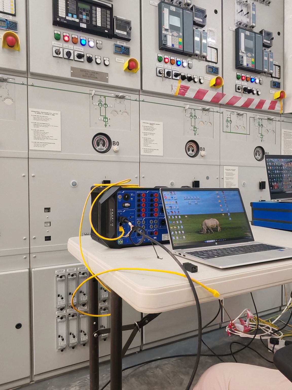
3. Test tool preparation Relay protection tester &; A cable for transmitting current, voltage and switching value; A ground wire; Digital multimeter; Screwdriver; Short wiring
2. Fixed value setting before debugging
2.1 According to the values of the current transformer and voltage transformer in the cabinet, set the transformer values in the protection device;
2.2 According to the fixed value sheet, set the corresponding protection kinetic energy input and withdrawal and the action value and action time of the protection function;
2.3 Connect one end of the cable transmitting current and voltage to the collection terminal of the protection current and protection voltage on the terminal block, and connect the other end to the relay Current and voltage output terminals of the protective device tester;
2.4 Ground the relay protection tester.
3. Debugging content
Debug the protection function according to the protection function invested in the fixed value sheet.
4. Debugging steps
4.1 Protection against jumping test
Calculate according to the protection starting value given in the fixed value sheet (multiply the starting value by 0.95), and pass the relay protection test according to the calculated value
The instrument adds the analog quantity to test whether the test is successful.
4.2 Protection jump test
Calculate according to the protection starting value in the customized sheet (multiply the starting value by 1.05), and pass the relay protection tester according to the calculated value
Increase the analog quantity to test whether the test is successful.
4.3 Non-electrical test
Non-power alarms and non-power jump sniffs collect external signals. When the protection device collects alarm signals or jump sniffs,
An alarm or jump signal will be output inside the protection device. Generally, the input end point is shorted through a short wire, so that
The protection device picks up an external signal.
4.4 Remote control test
Carry out the remote control test through the remote control closing and remote control opening buttons on the protection device to see if the test is successful.
5. Issues that need attention during debugging
5.1 Before debugging, it is necessary to confirm whether the value setting of the transformer is consistent with the value of the transformer in the cabinet;
5.2 Check whether the protection function is correctly put into operation and whether the protection action value and protection action time are correctly set according to the setting value sheet.
6. Analysis and summary after debugging
Data recording of protection operation values (start-up values, operation time) is performed by event recording in the protection device or test recording in the relay protection tester. Analyze the deviation between the data recorded in the test and the fixed value sheet to see if it is within the allowable deviation range.
7. Exception handling
7.1 Protective device abnormal
If there is protection malfunction or protection refusal during the test. When there is an abnormal phenomenon, it is necessary to review the setting sheet to see if the setting value is wrong;
7.2 Circuit Anomalies
When the output voltage or current of the relay protection tester reaches the protection starting value, the protection device has no action and there is no error in the setting value, it is necessary to check whether there is an open circuit or open circuit problem in the secondary circuit.
To sum up, the on-site debugging of relay protection devices is a complicated and meticulous work. Through careful preparation and careful execution of debugging steps, we can ensure that the device plays its due protective role in the power system and provide a strong guarantee for the safe and stable operation of the power system.