a- Test objective:
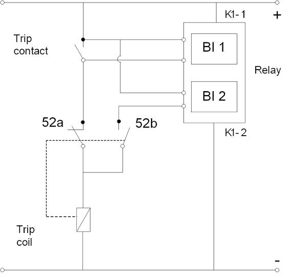
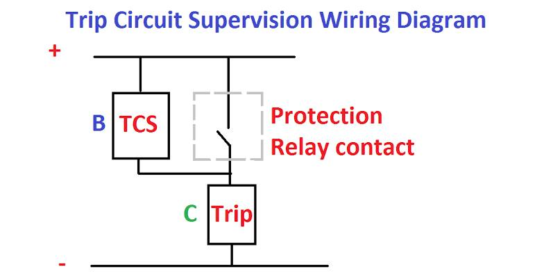
This test aimed to test trip circuit supervision which supervises the trip circuit and shows if it’s healthy or has any lose or disconnected wires in the trip circuit, in each panel there are two trip circuit supervision, first one to supervise trip circuit one and the other to supervise trip circuit two.
b- Testing Equipment Requirement:
1. Sverker (used as Voltage source and used its voltmeter).
2. Fluke [used as Ammeter].
3. Miniature Circuit Breaker 2Pole (2MCB).
c-Mechanical checked and visual inspection: 1. Check for physical damage or defects.
2. Checked tightness of all connections.
3. Checked ferrules.
d- Test connection and test procedure:
i. Check all Contacts:
1. Before injecting any voltage on relay’s Coil, check contacts at its normal condition which mean Normally Open (NO) contact is being opened and normally closed (NC) contact is being closed.
2. Inject the desired control voltage of coil (which is in our case 125 volt DC), at which Aux. relay will pick up that’s mean its contact will change its position i.e. NO contact will be closed and NC contact will be opened.
ii. Pick up and drop off currents and voltages: 1.03 Pick up voltage can be measured using voltmeter by increasing voltage gradually from 0 volt up to the relay will be operated (i.e. Contacts change its normal status, NO contact should be closed and vice versa) at a certain voltage. This voltage is called pick-up voltage, Record reading of V and A which is pick-up voltage and current. Drop-off voltage can be measured using voltmeter when the relay in an operate status and then decrease voltage gradually, the relay will release (i.e. its contact will return to its normal status) at a certain voltage. This voltage is considered drop-off voltage, Record the reading of voltmeter and Ammeter which is dropoff voltage and current.
iii. Resetting time:
• Adjust voltage source at relay rated voltage (in our case 125 v DC).
• To get resetting time, adjust the voltage source at 125 volt DC and switch MCB OFF.
iv. Burden test:
1. Adjust voltage source (sverker) at 125 volt DC, select on position and make MCB ON Record reading of Ammeter.
2. Calculate burden by multiplying coil operated voltage and reading of Ammeter.
3. Same pervious procedure for each coil.
4. Connection Diagram of Trip Circuit Supervision.
