


Understanding the Single Line Diagram for an Outgoing Feeder Transformer
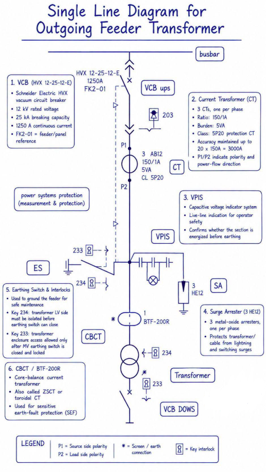
A single line diagram (SLD) is the universal language of power system design. It distills a complex three-phase network into a clean, one-line representation that engineers, operators, and protection specialists can read at a glance. The diagram shown here illustrates a typical **outgoing feeder transformer** arrangement — a standard configuration found in medium-voltage (MV) switchgear assemblies worldwide.
Let’s break down every component, from the busbar down to the transformer, and understand how each element contributes to safe, reliable, and protected power delivery.
---
1. Vacuum Circuit Breaker (VCB) — The Heart of Control
At the top of the feeder, directly off the **busbar**, sits the **Schneider Electric HVX 12-25-12-E vacuum circuit breaker** (designated FK2-01). This is the primary switching and protection device for the outgoing feeder.
The VCB performs two critical jobs:
- Normal switching**: Energizing and de-energizing the transformer under load.
- Fault interruption**: Instantly clearing short-circuit faults to prevent equipment damage and fire hazards.
Vacuum interruption technology is chosen here because it requires minimal maintenance, has a long electrical life, and eliminates the environmental concerns associated with SF₆ gas.
---
2. Current Transformer (CT) — The Eyes of Protection
Just downstream of the VCB, three Current Transformers (CTs) — one per phase — are installed. The specification reads:
- Ratio: 150/1 A
- Burden: 5 VA
- Class: 5P20 protection CT
What does this mean?
A150/1 A ratio means that when 150 A flows through the primary conductor, the CT outputs 1 A to the secondary side. This stepped-down current is safely fed to protection relays and metering instruments.
The 5P20 accuracy class is crucial for protection applications:
- 5 = composite error ≤ 5%
- P = protection class
- 20 = accuracy limit factor — the CT maintains its declared accuracy up to 20 × rated current (20 × 150 A = 3,000 A)
This ensures that even during severe fault conditions, the protection relay receives a faithful representation of the primary current and trips decisively.
The markings P1 (source side) and P2 (load side) indicate polarity, which is essential for directional protection schemes and correct power-flow measurement.
---
3. VPIS — Voltage Presence Indicating System
Safety in MV switchgear begins with knowing whether a conductor is energized. The VPIS (Capacitive Voltage Indicator System) provides a clear, reliable live-line indication for operator safety.
Before any maintenance work begins, technicians can visually confirm whether the feeder section is energized. This is a fundamental layer of personnel protection and a prerequisite for safe earthing procedures.
---
4. Surge Arrester (3 HE12) — Lightning & Switching Surge Protection
Connected to the feeder are three metal-oxide surge arresters (type HE12), one per phase. These devices act as silent guardians against:
- Lightning strikes on overhead lines
- Switching surges generated by breaker operations
- Temporary overvoltages
Under normal conditions, the arrester presents a very high impedance. When a surge arrives, it clamps the voltage to a safe level and diverts the surge current to earth. Once the threat passes, it returns to its high-impedance state automatically — no fuses to replace, no manual reset required.
---
5. Earthing Switch & Interlocks — The Safety Lock
Before anyone opens a transformer enclosure or performs cable work, the feeder must be grounded. The earthing switch (ES) serves exactly this purpose.
However, grounding an energized feeder would create a catastrophic short circuit.
This key interlock system (denoted by the padlock symbol 🔒) enforces a physical, foolproof sequence of operations. It eliminates human error and ensures compliance with safety regulations like LOTO (Lockout/Tagout) principles.
---
6. CBCT / BTF-200R — Sensitive Earth-Fault Detection
At the cable entry to the transformer, a Core Balance Current Transformer (CBCT) — also known as a Zero-Sequence CT (ZSCT) or toroidal CT — is installed. The model shown is the BTF-200R.
Unlike phase CTs that measure line currents, the CBCT encircles all three phase conductors. Under healthy, balanced conditions, the vector sum of the three-phase currents is zero, and the CBCT outputs nothing.
But when an earth fault occurs, current leaks to ground. This creates an imbalance — a zero-sequence current — which the CBCT detects with extreme sensitivity. This signal is fed to a protection relay that triggers an instantaneous trip, protecting personnel from touch potentials and preventing insulation damage.
---
Conclusion
For engineers designing MV switchgear, technicians commissioning substations, or procurement specialists evaluating feeder panels, understanding this diagram is non-negotiable. It is not merely a drawing — it is a blueprint for safety, protection, and operational continuity.
The outgoing feeder transformer SLD represents industry best practice: proven Schneider Electric switching equipment, properly specified protection CTs, multi-layered surge and earth-fault protection, and rigorous mechanical interlocking that puts personnel safety above all else.
Whether you are building a new substation or auditing an existing one, always read the SLD carefully. Every symbol, every annotation, and every rating tells a story — and in power systems, missing that story can be costly.