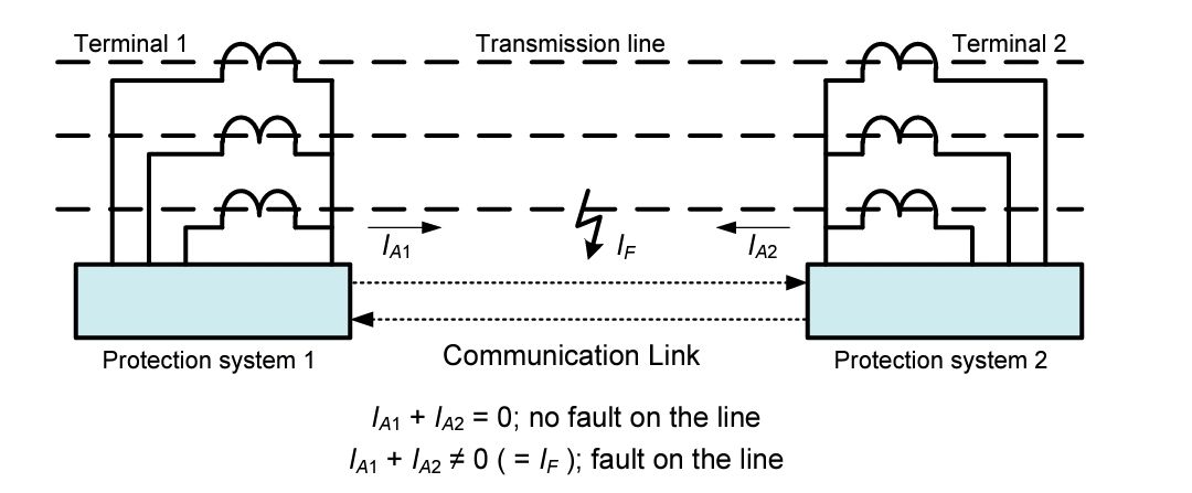


A basic current differential scheme is shown in the Figure . Information from the relay at the remote terminal is provided to the local relay using a communications channel. This information is compared with the corresponding information collected by the local relay. When there is no fault on the line, the difference between the two sets of information should be zero or equal to the tapped loads on the line. In practice, this may not be the case due to CT errors, ratio mismatch, and line-charging currents. Information concerning both the phase and the magnitude of the currents at each terminal are needed at all terminals for comparing the magnitude and phase angles and performing differential measurements. A current differential scheme, therefore, requires a communication channel suitable for the transmission of this data. A current differential scheme can operate for internal faults even for zero infeed at one or more of the terminals provided the total current is greater than the sensitivity of the differential protection system. There are two main types of current differential systems. The first type combines the currents at each terminal into a composite signal and compares these composite signals through a communication channel to determine if there is a fault in the line being protected. An example of this type of system is the ac pilot wire protection scheme described in 6.3.3. The second type samples individual phase currents at each terminal, converts the samples to a digital signal, and transmits these signals between terminals to determine if a fault is present on the line. The second type of differential system, referred to as phase-segregated line differential relays, includes most digital current differential relays. Specific measuring principles used in digital current differential protection schemes include percentage differential, charge comparison, and alpha plane principles. Current differential schemes tend to be more sensitive than distance-type schemes because they respond only to the currents in the protected line. However, either tapped loads on the line must be included as specific currents summed in the differential scheme or the relay current trip setting must be desensitized to compensate for any tapped loads that are not included in the current summation. Because current-only schemes require no potential to operate, they are not affected by system swing conditions or any problems introduced via the potential inputs, such as the failure of a voltage-transformer fuse. On the other hand, these schemes have no inherent remote backup capabilities. The integrity of the communication channel is very important to the operation of current differential schemes. For this reason, the communication channel should be highly reliable. Because the trip logic in current differential schemes generally does not rely on permissive or blocking elements, channel communications losses may cause misoperations; therefore, current differential protection schemes employ communications channel supervision to block potential misoperations from loss of communications. The advantages of current differential schemes are summarized as follows: • No VTs needed • Good for multi-ended lines • Can detect high resistance faults • Immune to power swings, current reversals, and high load flows • Uniform trip time for all line faults without misoperation due to overreach • No problems with series compensation • Simple to set with no coordination problems A summary of the disadvantages of current differential schemes includes the following: • No inherent remote backup capability • Trip current setting may need to be desensitized to account for tapped line load • Cost and complexity of communications channel having suitable requirements for the scheme • Trip output must be disabled for loss of communications Current differential schemes need a communication channel for exchanging information, such as power system frequency signals, audio tones, or digital and binary data, such as a transfer trip. Communications media can be metallic pilot wires, dedicated fiber optic links, T1(E1)/SONET (Synchronous Digital Hierarchy) communications networks, or Ethernet networks. Some digital current differential schemes have been operated on audio tones over leased telephone lines or digital microwave. Power-line carrier channels are generally not used for current differential relaying because either they do not have the bandwidth required by these schemes or there are other technical limitations of power-line carrier that makes it unsuitable for the particular application.